Altimeter and Flight Simulator Solutions
05/26/2021
Join us at Satellite 2021
09/01/2021RFOptic offers programable RFoF links up to 6 GHz. The user can modify the System Link Gain and Noise Figure by adjusting the internal LNA and attenuator settings through the User Interface
The Tx and Rx modules have micro-USB port through which the user can connect and change settings
RFOptic’s Link Gain Calculator made of 2 sections is used to determine how various settings and RF input signals affect RF and Optical links budgets. The left section is to input the RFoF link configuration as well as the specs of the RF input signal
In the Input section the user has to first determine for which RFoF link type they would like to run this calculator: 6 GHz, 3 GHz or 2.5 GHz RFoF link
Before changing anything else on the Link portion of the Input section, it is recommended that the user enters the RF input signal specs such as the Power and Bandwidth to the Signal portion. Tx Optical Power and Rx Optical Alarm can be kept at default vales.
After changing any parameters in the Input section, the Enter key has to be clicked to see the effects on the output Parameter Results section
Example 1

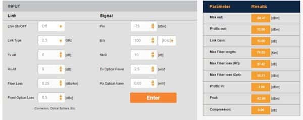
This example is for the 2.5 GHz RFoF link. LNA is off and Tx and Rx attenuators are set to 0. The input signal is -75 dBm with a 100 KHz bandwidth. The RFoF link will transport this signal since the output RF signal (Pout) is larger than the Minimum Detectable Signal (MDS) at the output
Example 2
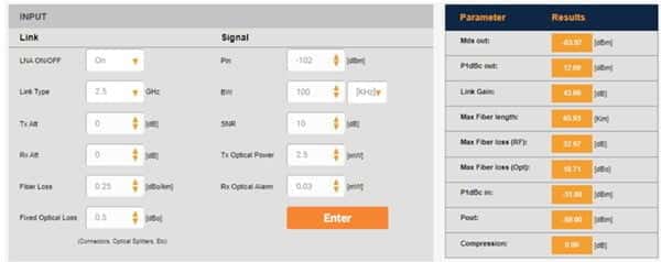
If the RFoF link is used to carry a very weak signal, it is better to turn on the LNA as can be seen in this scenario

Although the signal is very weak, the LNA provides an additional +30 dB gain on top of the +13 dB link gain. As in the previous example since the Pout is larger than the MDS, this signal can be transported using the RFoF link
Optical Link Budget
RFOptic’s Link Gain Calculator can also be used to calculate the max fiber cable length that can be used. In the last example, the fiber length can be up to 65 km. The quality of the fiber cable and the additional potential optical losses stemming from fiber patch panels and/or connectors can be modeled under the Input section and how they affect max fiber length and other optical parameters can be seen under the Parameter Result section
