Fiber Delay Spools
- Our fiber spools are used to create delays from tens of nanoseconds up to hundreds of microseconds
- Optional integrated DCF (Dispersion Control Fiber) if required
- Our engineers can assist you in spec’ing the appropriate delay line and RFoF transceiver in designing a delay line solution
- Pass through connector option to eliminate the need for patch cables and reduce optical loss
- Delay accuracy of <0.1% or better
- Custom connectors: FC, SC, LC, ST and APC/UPC type
- 1 km of single mode fiber provides approximately 5 uS delay
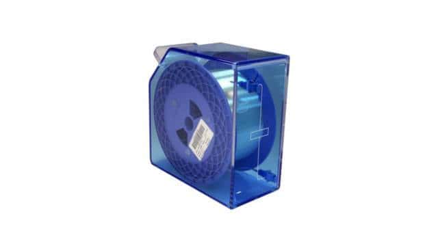
Compact Spools
- Option 1 – Up to 1 Km (5 uS) – Dimensions 6“ x 4.5“ x 1"
- Option 2 – Up to 6 Km (30uS) – Dimensions 8.25“ x 7“ x 1.5"

Portable Spools
FL8 Enclosure (10“ x 10“ x 5“)
- Up to 30 Km (150 microsec)
FL16 Enclosure (10“ x 10“ x 10“)
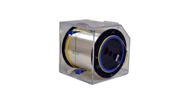
- Up to 60 Km (300 microsec)
Modular Chassis Based Spool Systems
FL-Flex (6 RU Chassis)
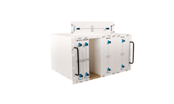
- Up to 9 modules totaling 240 km (1,200 microsec)
FL-TFlex (6 RU Enclosure)
- Up to 3 modules totaling 80 km (400 microsec)
- Modules are interchangeable with the 6RU chassis
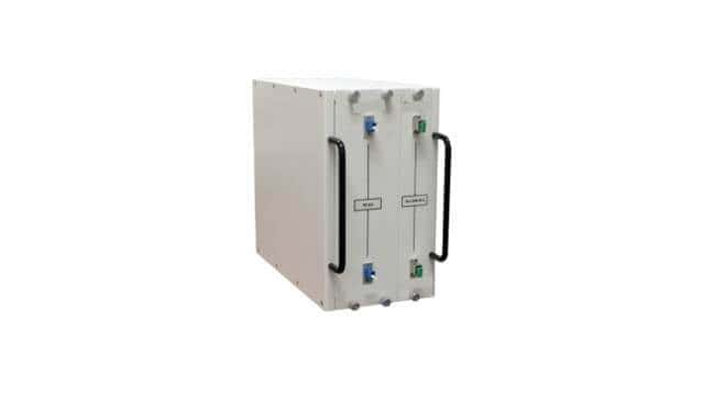
Fixed Chassis Based Spool Systems
FL250 (1 RU Chassis)
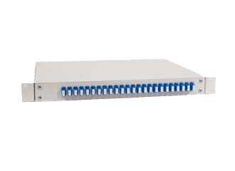
- Up to 12 spools totaling 30 km (150 microsec)
- Fixed spools
FL750 (3 RU Chassis)
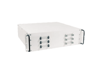
- Up to 6 spools totaling 150 km (750 microsec)
- Fixed spools
Applications
Fiber delay spools can be used in many applications
Fiber Optic Delay Lines are used to simulate distances. One specific application is radar and altimeter simulation/calibration. Standalone delay spools can be used along with an RF Over Fiber transceiver to form various inexpensive optical delay line setups:
- Single delay line
- Multi-delay line
- Variable delay line


RFoF Links Per Frequency Band
| Band | Frequency Range | Band | Frequency Range | Band | Frequency Range |
|---|---|---|---|---|---|
| HF | 3 MHz to 30 MHz | L band | 1 to 2 GHz | X band | 8 to 12 GHz |
| HF | 30 to 300 MHz | S band | 2 to 4 GHz | Ku band | 12 to 18 GHz |
| HF | 0.3 to 1 GHz | C band | 4 to 8 GHz | Ka band | 26 to 40 GHz |
Fiber Network Span Simulation:
Bare fiber spools are used to replicate fiber network spans. This enables engineers to measure the optical characteristics, such as delay and loss, of hundreds of km-long fiber network spans in a lab environment.
